This post is going to be a bit different, as it will not necessarily be focused on a particular application (it will have some context to it, though). I am going to focus on enabled subsystems and how to integrate them with merge blocks in order to compute variables.
First of all, let's start by seeing what a subsystem is: a subsystem is a set of blocks that have been grouped together in order to simplify the representation of a diagram. We will only consider virtual subsystems right now. A subsystem creates a graphical hierarchy and all blocks within are visible and accessible by double clicking on it and accessing the corresponding level of the created visual hierarchy.
We can create an empty subsystem from the Simulink Library and populate it with blocks or we can drag our cursor over multiple blocks, right click and create a subsystem from our selection. If there are unconnected lines or unconnected I/Os of the blocks involved in the subsystem creation, inputs and outputs will automatically be created within the subsystem and connected to these lines/ports.
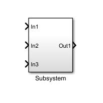
In the example below, the resulting subsystem (right) will have 3 inputs and one output that will be created automatically.
If no specific scheduling is specified at the subsystem level or a parent level, the calculations within the subsystem will execute every simulation step. While it's ok that we don't have to worry about our subsystem not being taken into account when computing, this behavior is not always ideal.
What if we wanted to compute a variable in two different fashions, depending on a certain situation? One might say that you could use a switch, but it's not always indicated.
What if we had two strategies in mind on how to compute a variable within a vehicle's ECU, but one strategy requires a certain type of sensor (like a camera, for example), that is only available on higher specs of the car? We could construct two different models that would translate into different software components, each to be integrated in the ECU of its respective vehicle configuration, but this would take more time and effort. We would have to maintain and update two models instead of only one, we would have to make sure that the outputs correctly communicate with other SW components in both cases, and in case of a difference in variables names, we might have to include macros in order to correct any deviations in names and such.
In such cases, we usually use a calibration that enables one of two strategies, depending on its value.
Each strategy could be computed within an Enabled Subsystem. Such a subsystem only computes its outputs when the enabling condition is true.
In order to create an Enabled Subsystem, we could either create it from scratch using the Library Browser, or we could convert a conventional subsystem into an enabled one using an Enable block.
In the example above, I've first created a subsystem that computes the average of two inputs. Afterwards, I've added an Enable block in order to condition its execution. Now, the subsystem will have an additional port on its upper side that needs to be connected, in order for its contents to be executed.
Let's see an example model, in order to better understand how it works.
In the example above, the value of the "Complex_strategy" calibration is used to determine whether Out1 will be the arithmetic average of In1 and In2 or a weighted average (set to 0.4 for In1 and 0.6 for In2). When it is set to 0, we will use the Simplified_comp subsystem. Else, we will use the complex computation in the above subsystem.
Note that both outputs are fed to a Merge block. This block will propagate the output of whichever subsystem is enabled, towards the Scope (it can be any other type of block). Thus, we avoid creating two separate variables, since we only have one output of interest, but computed in two different ways.
Merge blocks are not limited to only two inputs, the user may use as many as he wishes. What is extremely important is to ensure that only one input is propagated towards the merge, at any given time. In our case, we need to ensure that the conditions enabling the two subsystems may never coincide, under any given circumstances.
Let's see an example of how improper conditions may lead to simulation errors. In the example below, step is set to pass from 0 to 5 at 3s. Since the two conditions are not mutually exclusive, they are both met, and both outputs of the two subsystems are fed to the merge block at the same time. This will result in a simulation error, since the model cannot chose between the two.
So, to summarize:
- there are certain situations where it is preferable to work with Enabled Subsystems (choosing between strategies or applying different operations to the same variable, depending on an external condition);
- an Enabled Subsystem will only execute its contents while the enabling conditions is true;
- we can merge the outputs of Enabled Subsystems using a Merge block (whichever strategy is used will be propagated towards the output of the Merge);
- we must be very careful to ensure that the conditions that compute the inputs of the same Merge block do NOT take place at the same time, under any circumstances.
That should be it for now. Next time, we will take a look at a different approach to compute the contents of Subsystems only under given circumstances, by using function calls.